K-2418 · Food production unit, Runcorn
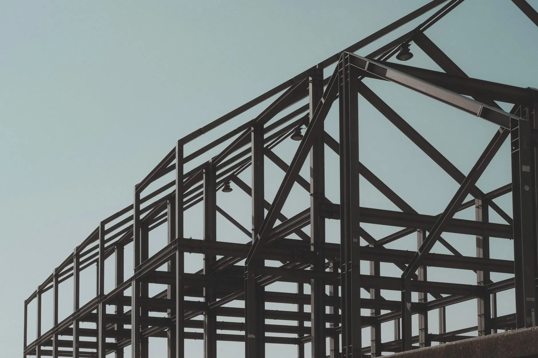
Mezzanine and access stair
Beams, columns and a 26-tread stair with a landing, blasted and primed in the shop, erected over two weekend shifts so the production line never stopped.
11.4 t18 working days
Steel fabrication in Liverpool since 1987
Kanwick is a 38-person job shop for contractors, architects and manufacturers. Send a drawing today; get a price in 2 working days and finished steel in 15 working days.
Priced in 2 working days
Send a DXF, a PDF or a sketch. A named estimator prices it and calls back with questions, not a form letter.
Drawing to delivery in 15 days
Standard fabrication, from approved drawings to steel on your site. Laser-only work often ships in five.
EXC2, CE marked, traceable
Every structural job leaves with mill certificates, weld records and a declaration of performance.
Our own wagon and hiab
Delivered by the people who made it, across the North West and North Wales, on a booked slot.
What we make
Most jobs touch three or four of these. Because they are all in one building, you get one quote, one lead time and one person to call.
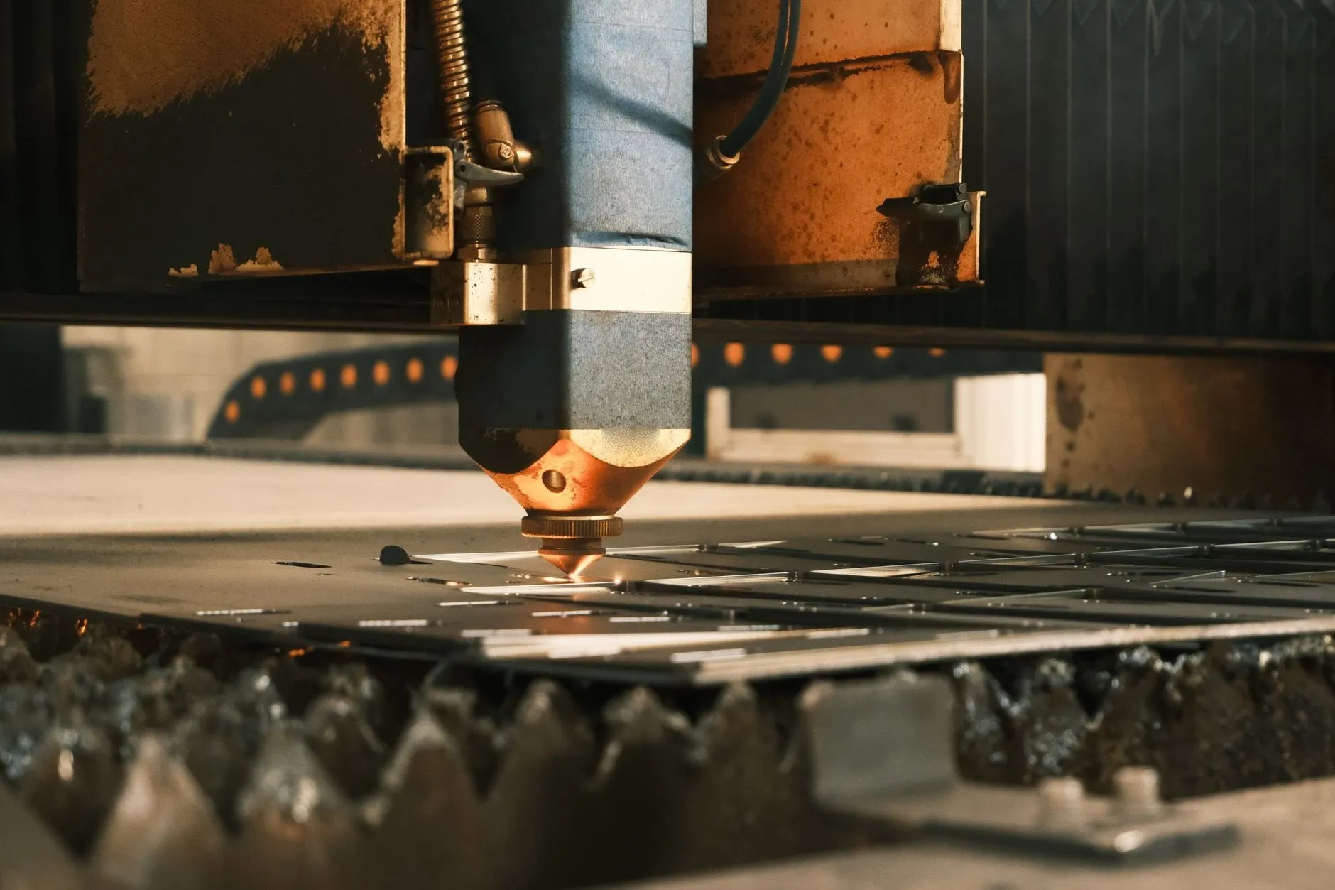
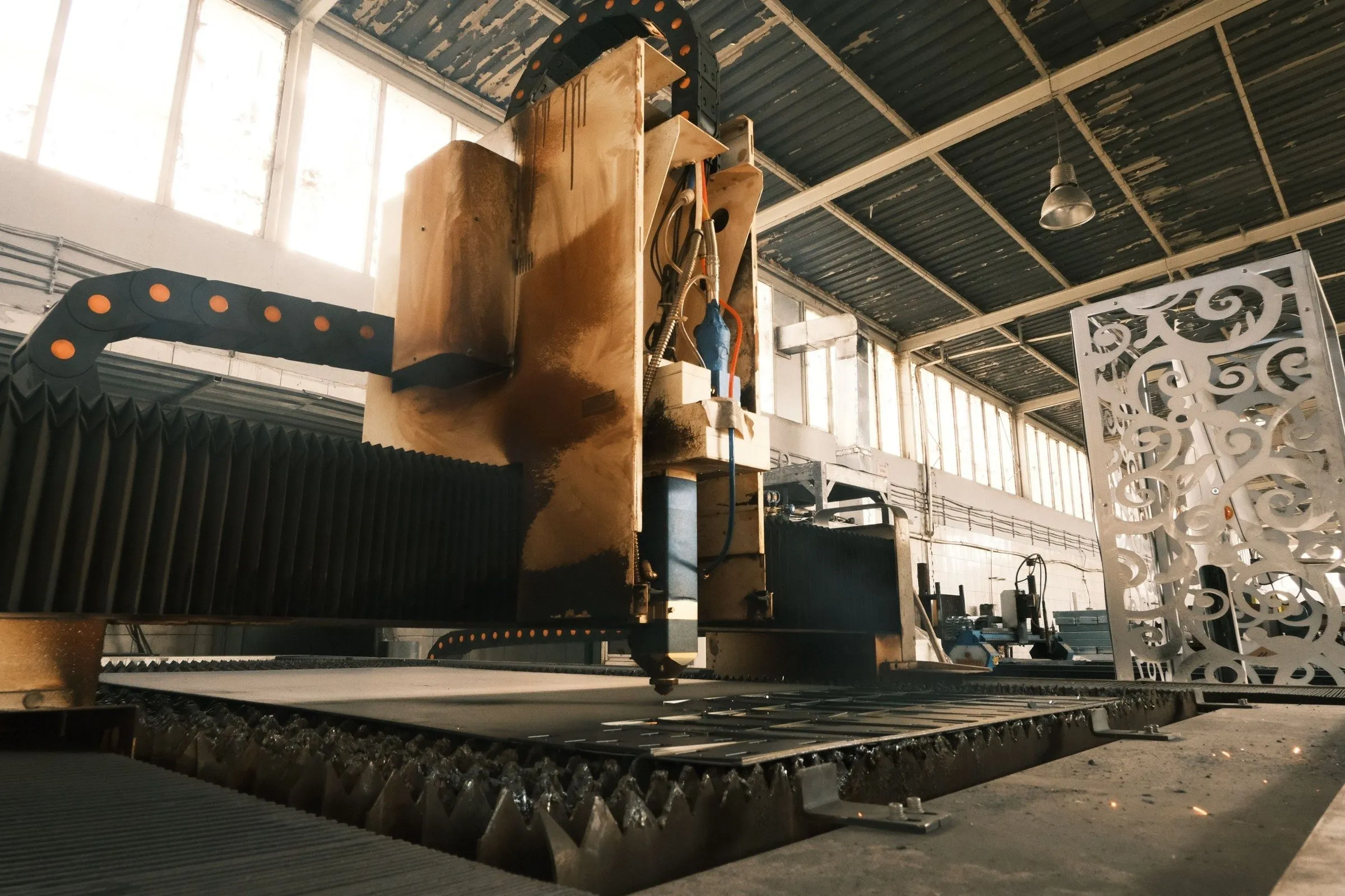
A 6 kW fibre laser on a 3,000 × 1,500 mm bed. Mild steel to 25 mm, stainless to 20 mm, aluminium to 16 mm, cut to ±0.1 mm straight from your DXF.
From £45 per order of simple parts
5 working days
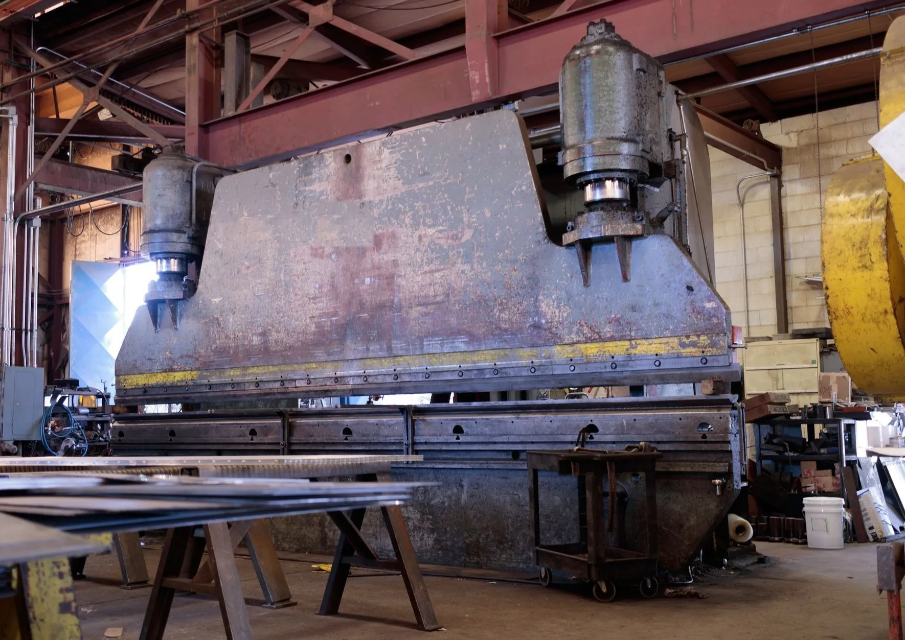
A 160-tonne CNC press brake with a six-axis back gauge. Folds up to 3.2 m in one hit, first-off parts measured before the batch runs.
From £1.20 per bend, plus £35 set-up
7–10 working days
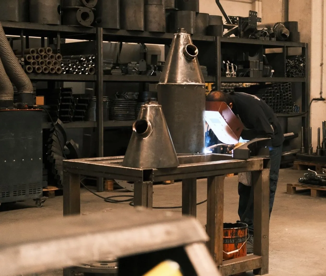
MIG, TIG and MMA in five bays, by welders coded to BS EN ISO 9606-1. Frames, brackets, chassis, tanks and one-off repairs at a £58 an hour shop rate.
From £58 per hour shop rate, £145 minimum
10–15 working days
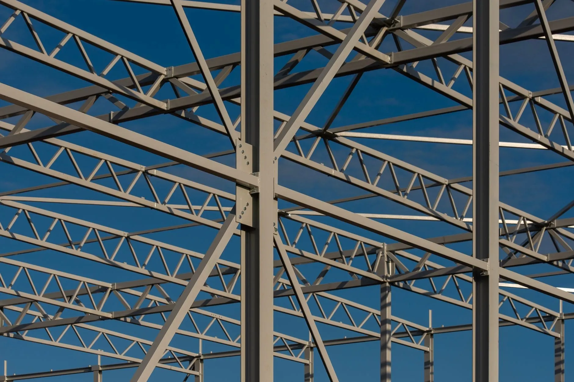
Beams, columns, bracing and baseplates fabricated to BS EN 1090-2 at EXC2, CE marked, blasted and primed, and erected by our own squad.
From £1,650 per tonne, fabricated and primed
15 working days
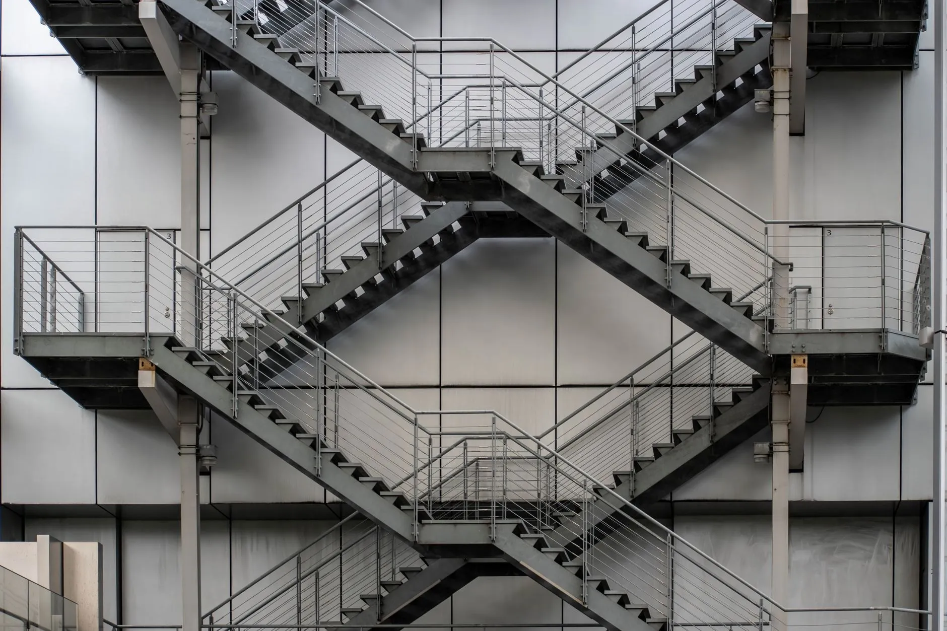
Escape stairs, feature stairs, handrail, balustrade and access platforms, designed to Part K, fabricated in-house and fitted by our own squad.
From £2,400 per straight flight, fitted
15 working days
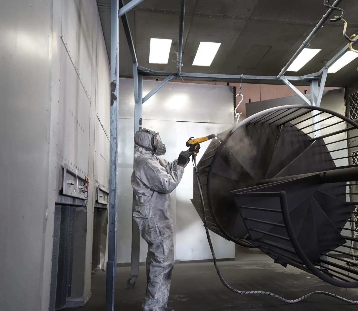
Blast to SA2½, then powder coat in any RAL colour in our own booth and 7-metre oven. Fine texture, gloss, satin and zinc-rich primer systems.
From £18 per m², £65 minimum per colour
3–5 working days
Capacity
Sheet sizes, thicknesses and tolerances for the machines most jobs run on.
| Machine | Max size | Mild steel | Stainless | Aluminium | Tolerance |
|---|---|---|---|---|---|
| 6 kW fibre laser | 3,000 × 1,500 mm sheet | 0.8–25 mm | 0.8–20 mm | 0.8–16 mm | ±0.1 mm |
| 160 t CNC press brake | 3,200 mm bend length | to 10 mm (12 mm at 1.5 m) | to 6 mm | to 10 mm | ±0.5° |
| Bevel plasma table | 3,000 × 1,500 mm plate | 3–40 mm | 3–25 mm | 3–20 mm | ±0.5 mm |
| Welding bays (5) | Positioners to 1 t | MIG, MMA | TIG, pulsed MIG | TIG, pulsed MIG | EN ISO 13920 B |
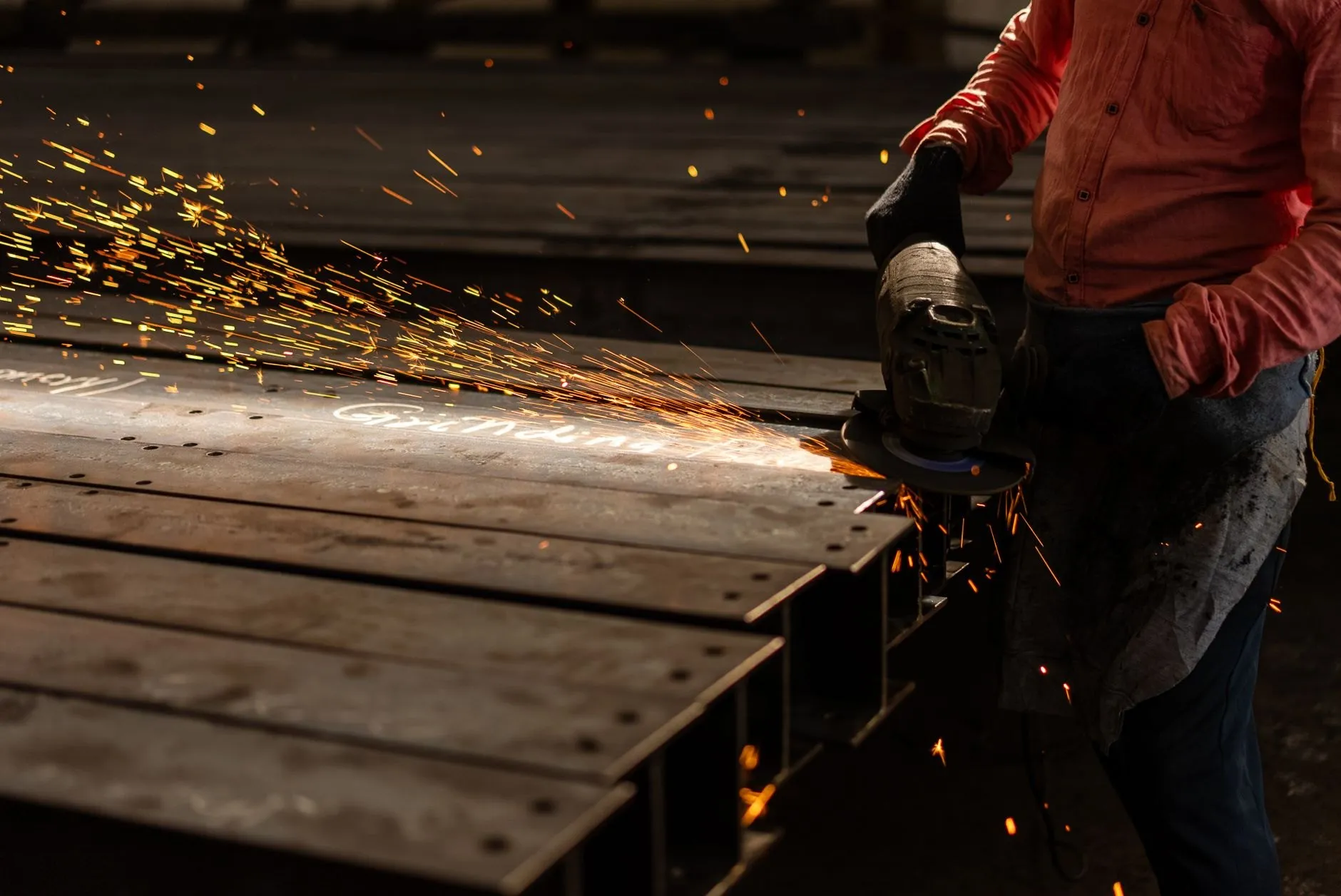
The works
Kanwick started in 1987 as two welders and a borrowed crane. Today it is 38 people in a 4,200 m² shop on the Liverpool docks, still run by the family, and still answering the phone before the third ring.
How a job runs
Six stages, and you sign off the drawings before any steel is cut.
You send a drawing, a model or a sample. We mark up anything unclear and price it within two working days.
Fabrication drawings come back to you for signature. Nothing is cut until that signature does.
Laser, saw and brake. Every part carries its mark number and the cast number of the plate it came from.
Welded to procedure by coded welders, then checked against the drawing before it leaves the bay.
Blasted and primed, powder coated in any RAL colour, or galvanised on a fixed three-day turn.
On our own wagon, on a booked slot, with the paperwork in the cab and a hiab where there is no crane.
Instant estimate
Pick the material, thickness, quantity and finish. You get a lead time and a price band now, and a firm quote once we see the drawing.
Why one works
A cutting bureau is quick for flat parts. A general fabricator subcontracts the rest. We do the lot in one building.
| Feature | Kanwick | Cutting bureau | General fabricator |
|---|---|---|---|
| Cut, fold, weld and coat | All under one roof | Cutting only | Usually subcontracted |
| Price back | 2 working days | Same day, per sheet | 5–10 days |
| Lead time | 5–15 working days | 3–5 days (cut only) | 4–6 weeks |
| EXC2 / CE marking | Yes, with traceability | No | Sometimes |
| Delivery and install | Own wagon and squad | Courier | Varies |
Recent work
K-2418 · Food production unit, Runcorn
Beams, columns and a 26-tread stair with a landing, blasted and primed in the shop, erected over two weekend shifts so the production line never stopped.
11.4 t18 working days
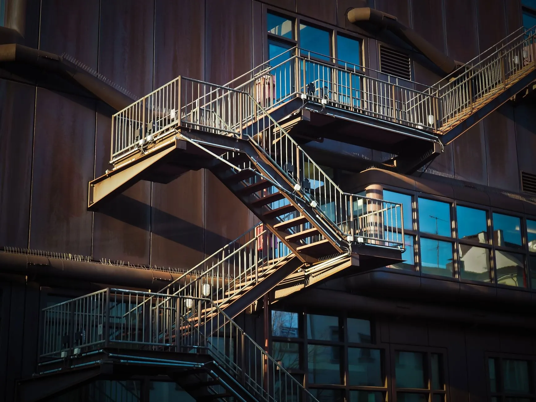
K-2402 · Office refurbishment, Liverpool
Four flights and landings with bar-infill balustrade, galvanised then powder coated to RAL 7016, bolted on without a single site weld.
7.9 t16 working days
From our clients
Main contractorsArchitectsFood productionRecycling plantsCold storageAgricultural machineryShopfittersHousebuilders
“We sent the steel package on a Tuesday and had a price with three sensible questions by Thursday. The mezzanine went up over two weekend shifts and the line never stopped.”
Dan R.
Contracts manager, Warrington
Job K-2418 · Mezzanine and access stair
“They built the balustrade to the fold detail we actually drew, not the nearest stock section. Samples on the bench a week before anything was cut.”
Priya S.
Project architect, Liverpool
Job K-2377 · Feature stair and balustrade
“Four hundred laser-cut brackets a month, folded and powder coated, and I have not had to chase a delivery in two years. That is the whole review.”
Mark T.
Production manager, Deeside
Call-off account since 2023 · 400 parts a month
4.9 out of 5 from 186 client reviews
Shop notes
Finishing · 21 August 2026 · 4 min
What each finish costs, how long it lasts outside, and why the answer for a stair on the coast is usually both.
Estimating · 30 July 2026 · 4 min
Six lines that turn a two-day quote into a two-hour one, and the two that cause almost every re-price.
Forming · 18 June 2026 · 5 min
Why the first part off the press brake gets measured, even when the certificate says it should not need to be.
Questions
Anything else goes straight to an estimator — call or email.
A drawing (DXF, DWG, STEP or a dimensioned PDF), the material and thickness, the quantity, the finish and the date you need it. A sketch with sizes is fine for simple work. We reply within two working days.
There is a minimum charge of £145 per order, which covers programming, set-up and one hour of shop time. One-off parts are welcome; repeat batches get cheaper per part as the set-up is shared.
DXF and DWG straight to the laser; STEP and IGES for folded parts, which we unfold ourselves; PDF for anything else. If all you have is a worn part, send it in and we will measure and draw it.
Laser-cut parts usually ship in five working days. Cut-and-folded work takes seven to ten, and standard welded or structural fabrication fifteen from approved drawings. A paid rush slot is often available — ask when you send the drawing.
Yes. We are certified to BS EN 1090-1 at execution class EXC2. Structural work ships with a declaration of performance, mill certificates traceable to cast numbers and weld inspection records.
Free on orders over £1,500 within 30 miles of the works. Elsewhere in the North West and North Wales it is a fixed £85 per drop on our own wagon, or £140 with the hiab.