Capacity
What fits, how thick, how close.
Check the size, thickness and tolerance here before you send a drawing. If a part is outside these numbers, ask anyway — we know who can do it.
Machines are serviced on contract and calibrated every six months. Calibration certificates are available on request for audited supply chains.
Machines and tolerances
Thickness ranges are for full-quality edges. Thinner and thicker are possible on request.
| Machine | Max size | Mild steel | Stainless | Aluminium | Tolerance |
|---|---|---|---|---|---|
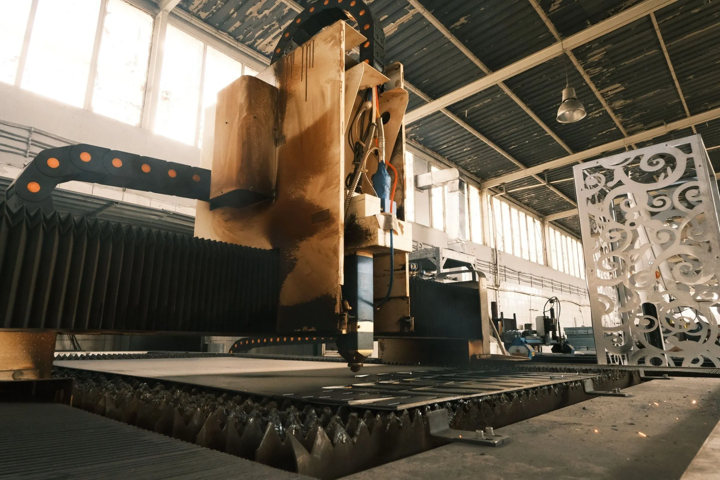
| 6 kW fibre laser | 3,000 × 1,500 mm sheet | 0.8–25 mm | 0.8–20 mm | 0.8–16 mm | ±0.1 mm |
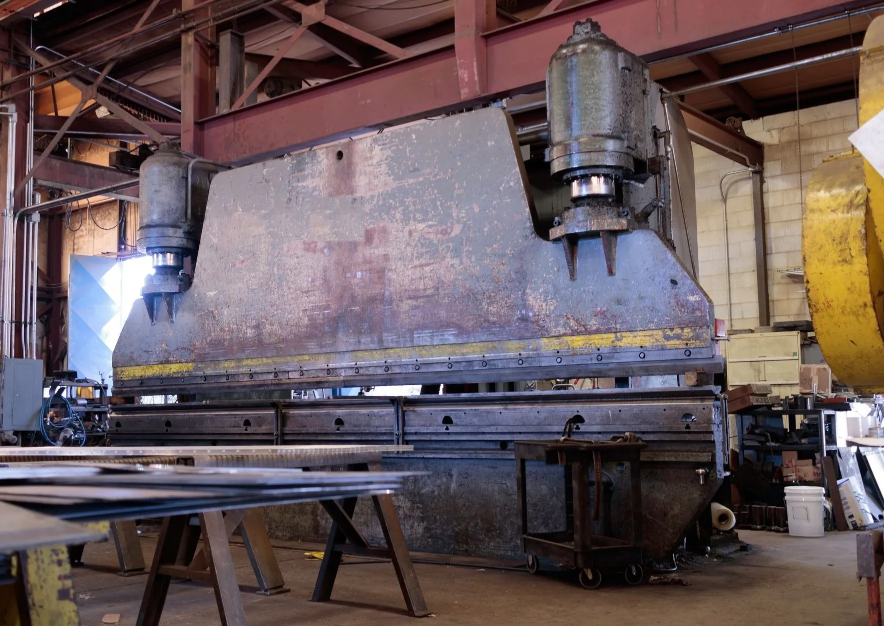
| 160 t CNC press brake | 3,200 mm bend length | to 10 mm (12 mm at 1.5 m) | to 6 mm | to 10 mm | ±0.5° |
| Bevel plasma table | 3,000 × 1,500 mm plate | 3–40 mm | 3–25 mm | 3–20 mm | ±0.5 mm |
| Welding bays (5) | Positioners to 1 t | MIG, MMA | TIG, pulsed MIG | TIG, pulsed MIG | EN ISO 13920 B |
| Mitre bandsaws (2) | 350 mm section, ±60° | All sections | Tube and bar | Extrusions | ±0.5 mm |
| Beam drill line | Sections to 12 m | Holes to 40 mm | — | — | ±0.5 mm |
| Powder booth and oven | 7.0 × 1.8 × 2.2 m | Blast SA2½ | Sweep blast | Pre-treated | 60–80 µm film |
| Overhead crane | 5 t, 12 m span | Lengths to 12 m | — | — | — |
Size limits
- Longest single piece
- 12 m
- Heaviest single lift
- 5 t
- Largest laser blank
- 3,000 × 1,500 mm
- Longest single fold
- 3,200 mm
- Largest item in the oven
- 7.0 × 1.8 × 2.2 m
- Wagon bed
- 13.6 m, hiab to 2.5 t at 8 m
Certifications
- BS EN 1090-1 Execution class EXC2
- BS EN ISO 9606-1 Coded welders, re-tested every 2 years
- BS EN ISO 3834-3 Fusion welding quality
- ISO 9001 Quality management
- CHAS Health and safety, assessed yearly
- Constructionline Gold Pre-qualified supplier